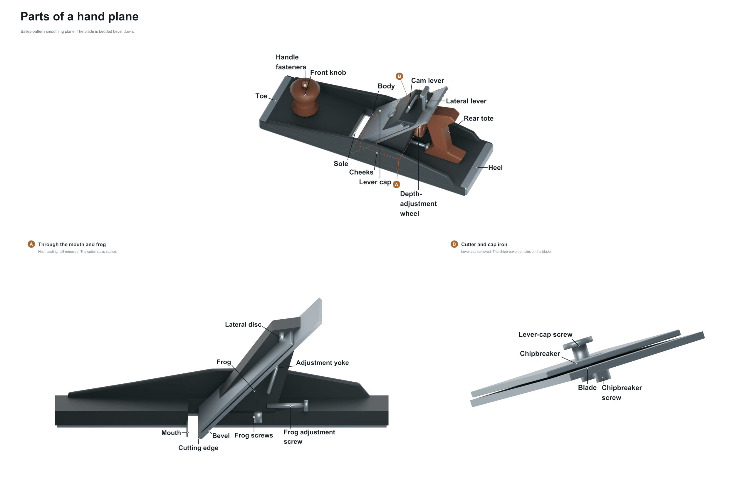
One of the basic tools in every woodworker’s toolbox is the hand plane. A hand plane remove very small amounts of wood to make a joint or edge square and smooth. While the tool may look like a simple block of metal and wood, it is actualy a finely tuned machine. But it is actually a well-made machine that has each part doing a specific job to control the cut.
If you take a closer look you will see a labeled drawing showing what all the pieces are called. Each one of them do something to turn rough lumber into refined lumber. Knowing what they do will help you care for your plane and set it up to get even better cuts.
Parts of a Hand Plane
Toe
The Toe is on the front of the plane body. That’s the leading edge of the plane which makes contact with the wood first. As you push the tool forward, the toe directs the plane forward and keeps it stable. When the Toe isn’t smooth and clean of any burrs, the plane will dig or catch unexpected into the workpiece.
Sole
The Sole is located just under the main structure. This is the flat bottom surface that rides along the wood. For the plane to make even shavings, the Sole needs to be perfectly flat. Any high spots or dents in the Sole will cause the plane to skip and create ridges in your work. To bring the Sole back to flat, lap it on a diamond plate or flat stone.
Mouth
Moving slightly back you come to the Mouth. This is the opening in the Sole where the blade protrudes to cut the wood. The size of the mouth affects the type of cut you can make. A wider mouth allows for deeper cuts and smoother finishing on straight-grained wood; a narrow mouth reduces tear-out when working with difficult grain.
Knob
Next comes the Knob which is usually at the front of the tool. This forward handle allow you to push the plane with pressure and control. Typically it’s located near the front as this helps keep the nose down and prevents the tool from diving into the wood. The knob needs to be tight enough to stay secure yet loose enough to adjust if the handle were to wear over time.
Frog
The Frog, The Frog is an angled block of metal that bolts into the body and supports the blade assembly. The blade’s cutting action is affected by the angle of the frog. For softer woods, use a shallower angle and for harder woods, use a steeper angle. The Frog must be properly seated and held secure against the body. When not properly seated or when loose, the blade will chatter and give you a rough surface on your workpiece.
Iron blade
There are basically two components to the cutting part. One is the Iron blade, which is the cutting edge of steel that cuts through the wood. It should be sharpened to a fine shaving edge so it slices through the wood cleanly without crushing the fibers.
Cap iron
The second component is called the Cap iron which rests on top of and behind the iron blade. Its purpose is to clamp the iron into position and also to help protect against tear out by severing the wood fibers before they reach the cutting edge. On knotty or figured wood it is very important to have the cap iron adjusted closely to the edge of the blade for a nice clean cut.
Lever cap
Next up are the blades. These are held by the Lever cap. The lever cap is a curved piece of metal that clamps down on the iron blade and cap iron. It holds them tightly to the frog. You want it tight enough so that when cutting, the blade doesn’t slide around causing an irregular cut. Often the lever cap will engage with a slot in the adjustment mechanism. That connects your hand movement to where the blade is positioned.
Depth adjustment wheel
The depth adjustment wheel is typically found on the rear of the frog. The entire blade assembly will move up and down as you turn the wheel. Retracting it gives you a finer shave, while turning it out exposes more blade to give you a deeper cut. With this you can precisely adjust the amount of material taken off in one pass.
Lateral adjustment lever
The lateral adjustment lever is next to the depth adjustment wheel. When pushed, it will move the blade a bit left or right. That’s good if you want to take a final light pass across a board to make sure the surface is perfectly level. It lets you fix small height differences but doesn’t change the overall depth setting.
Tote
Finally, at the rear of the plane, you will find the Tote. When pushing the plane, you use the tote to gain control and leverage. To help guide the plane along your intended line and to keep it stable, you push down through the tote. The tote may be shaped and positioned different depending on the type and size of the plane you are using. However, it still does the same thing.
Body
The heel is on the other end of the body from the toe. In other words, it’s at the very back of the body. It serves as a reference point for the sole’s flatness. This way, if you’re making really heavy cuts, the weight of the tool is distributed evenly across the plane.
Together they form one mechanical system. Anytime you find it hard to push the plane or it makes an ugly cut, look at this relationship between all the parts. Is the sole flat? The cap iron on tight? Blade sharp? Is the frog well bolted down? Are the adjusting mechanisms clean?
Knowing about the relationships of the knob, tote, frog, and blade assembly will help you diagnose issues and get back to work fast. That’s what makes the hand plane a trusted extension of your hands rather than a mystery.