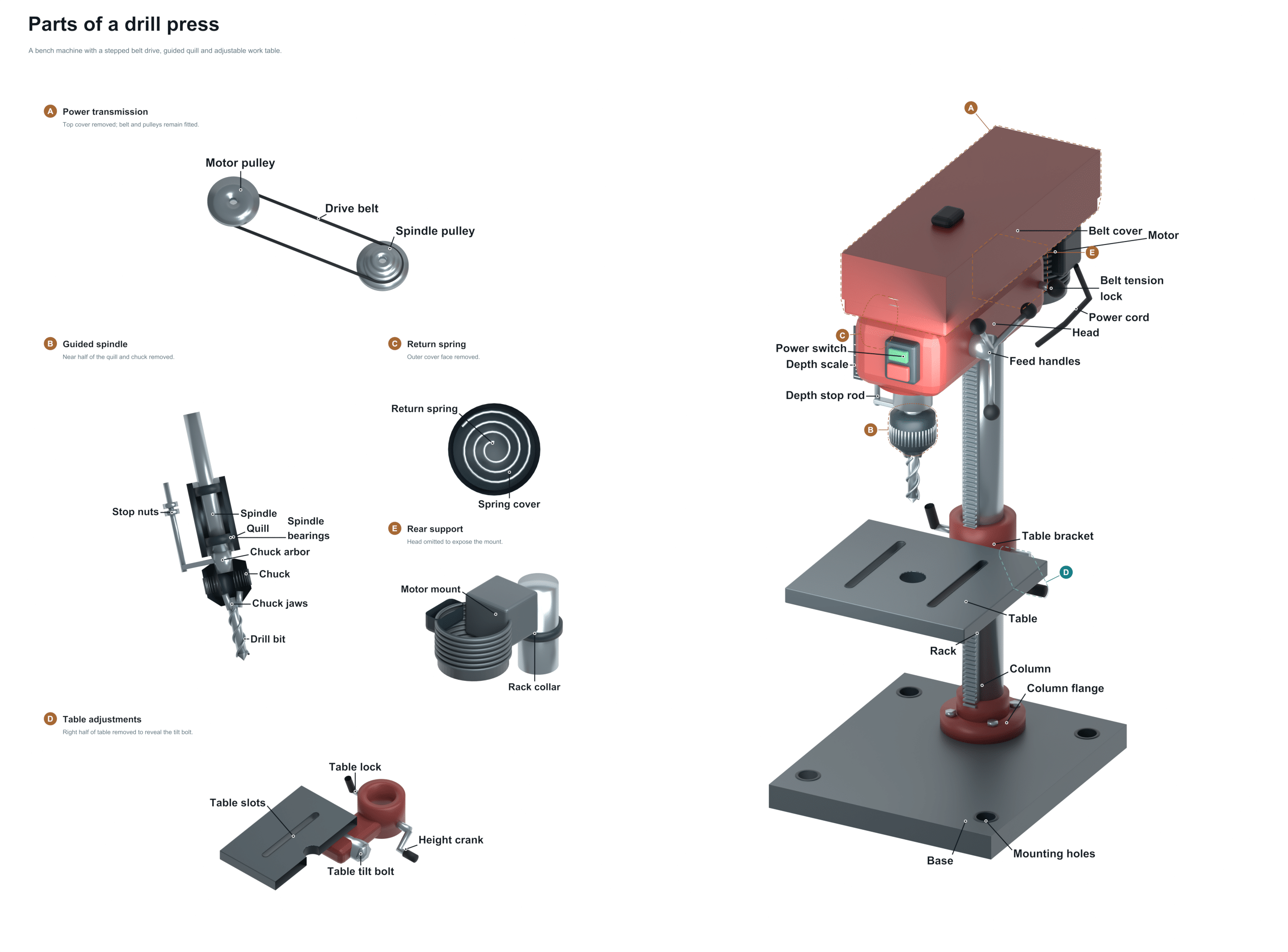
Many shops have a drill press which is a solid workhorse. It’s a tool used for drilling accurate holes in wood, metal, plastic, etc. Unlike a handheld drill, which relies on the operator’s stability and strength, a drill press provide a fixed axis and mechanical leverage. The beauty of a drill press is that there is mechanical advantage and a stationary vertical axis. That’s how it gives such reliable results. The drill press converts energy into rotating motion that is controlled. With this setup, making neat perpendicular hole is easy.
Here are explanations of its parts, so you know what everything does and can use the machine propery. Above is a labeled diagram of the main components. As you learn about them, use it as a guide to locate each part.
Parts of a Drill Press
Base
The base is typically a heavy cast iron base. It provides both vibration absorption and stability for the unit. Sitting on either the work bench or the floor, the base anchors the machine in place ensuring it doesn’t move while working. Having a solid base is critical when it comes to accuracy. If there is any wobble at this point it’ll translate into inaccuracies with your holes. Before you start any projects make sure the base is secure to your work surface and level.
Column
The Column rises vertically out of the base. It’s basically a rigid steel shaft supporting the moving head assembly. The column provides a guide for the head so it can move smoothly in and out along its axis (up/down). Lightly lubricate and clean the column. This will allow smooth motion vertically. The rigidity of this component dictate how well the machine will resist deflection while drilling into hard materials.
Head
At the top of the column is the Head which contains the transmission system and the motor. Within this housing, there are pulleys or gears that change the torque and speed sent to the spindle. A lever or other type of clamp holds it in position on the column and allows it to slide up and down. This becomes the primary moving part of the upper assembly so that the spindle can be raised and lowered relative to the table.
Motor
The Motor is located inside the head. This is what powers the rotation of the drill. The motor takes electrical energy and turns it into mechanical energy. By using either a gear or belt system, the motor turns the spindle. Wattage and size of this motor determine how big a hole you can drill with your machine. To be able to drill large holes in hard metal without stalling requires a strong motor.
Belt Cover
This is the belt cover. This protects the pulleys and drive belts that link the motor to the spindle. Without it, your tool could get hung up on hair, clothes, or other items as the belts turn. That is a big safety risk. It also blocks dirt and debris away from the transmission mechanism. Always leave this cover installed when operating the machine. Do so safely.
Switch
The Switch The switch is what controls the machine. Usually this is a toggle or button mounted on the motor housing or on the side of the head. When the switch is pressed the drill bit will turn. That means you have instant control of whether it’s turning or not. It is designed for quick access in case something doesn’t go right. Be sure the switch engages smoothly. When turned off it should of totally cut power.
Feed Handle
That’s the Feed Handle. Push it down and that pushes the spindle into the piece being worked on. It gives mechanical advantage which means you can apply a steady, controlled amount of pressure with not too much effort. The quill connects to the handle. And this lets you have accurate depth control while drilling the holes. After every hole, bring the handle back up to the highest point. That resets the mechanism.
Quill
The Quill is a tubular sleeve that houses the spindle and moves vertically. Quill is a tubular sleeve into which the spindle fits. It’s attached to the feed mechanism. The quill, in turn, attaches to a handle mounted on the head. When you push down on this handle, it drives the quill downward. It needs to do so freely with no slop or resistance. That allows for precise hole placement. Periodic lubrication of the quill can help keep it operating smoothly. It will also prevent wear on its internal parts.
Depth Stop
Depth Stop An adjustable collar limits how far down the quill goes. This way, each hole can be drilled to exactly the same depth every time. The stop is set on a pin or threaded rod and locks into place at whatever setting you want it. It is great for drilling many of the exact same holes in a row on several parts.
Spindle
The spindle runs through the center of the quill. The spindle is the shaft that spins while holding the cutting tool. Power from the motor gets transferred through the spindle to the drill bit and chuck. Precision bearings hold up the spindle. These minimize any vibration and give a true vertical rotation. When your spindle wears, there will be runout. This results in irregular or oversized hole.
Chuck
The Chuck The Chuck is at the business end of the spindle. The chuck is a clamp which tightly grasps the drill bit. To hold it in place when drilling you either use a key or your hand to tighten the chuck. Make sure there is no dirt or anything else on it so the bit’s shank can grip well. If the chuck is too loose, the bit may become unsteady and slip. It is not good, not accurate, and unsafe.
Parts of a Drill Press This is the actual cutting tool that will remove material to make a hole. It’s inserted into the chuck. As the drill bit pierces through the surface, it shears off wood or metal fibers as it spins very fast. The right bit must be chosen for your material. This ensures good results and a long life for the tool. Always make sure the bit is tightly secured before you apply power to the machine.
Table
The table is the flat surface below the head assembly where you place the work piece. The table rides up and down in the column. This brings the piece of wood to the appropriate height for the drill bit to reach. Often times it also tilts so you can perform angled drilling operations. Your work piece will be stable when drilling if you keep the table clean and flat.
Table Lock
The table lock is either the lever or knob that locks the table into place at the chosen height. After setting the table to your desired height, simply cinch down on the table lock and it will hold the table in place while operating. If the table lock isn’t tight, the material could slip around causing some of the holes to be off center or even hurt someone. Always make sure the table is secure before drilling.
Table Crank
A table crank raises and lowers the table manually. Using a rack and pinion gear system, it moves the table smoothly up and down the column. The height can be finely adjusted. Adjustments can match the thickness of the workpiece. Gently use the table crank. Avoid stripping the gears located within the table assembly.