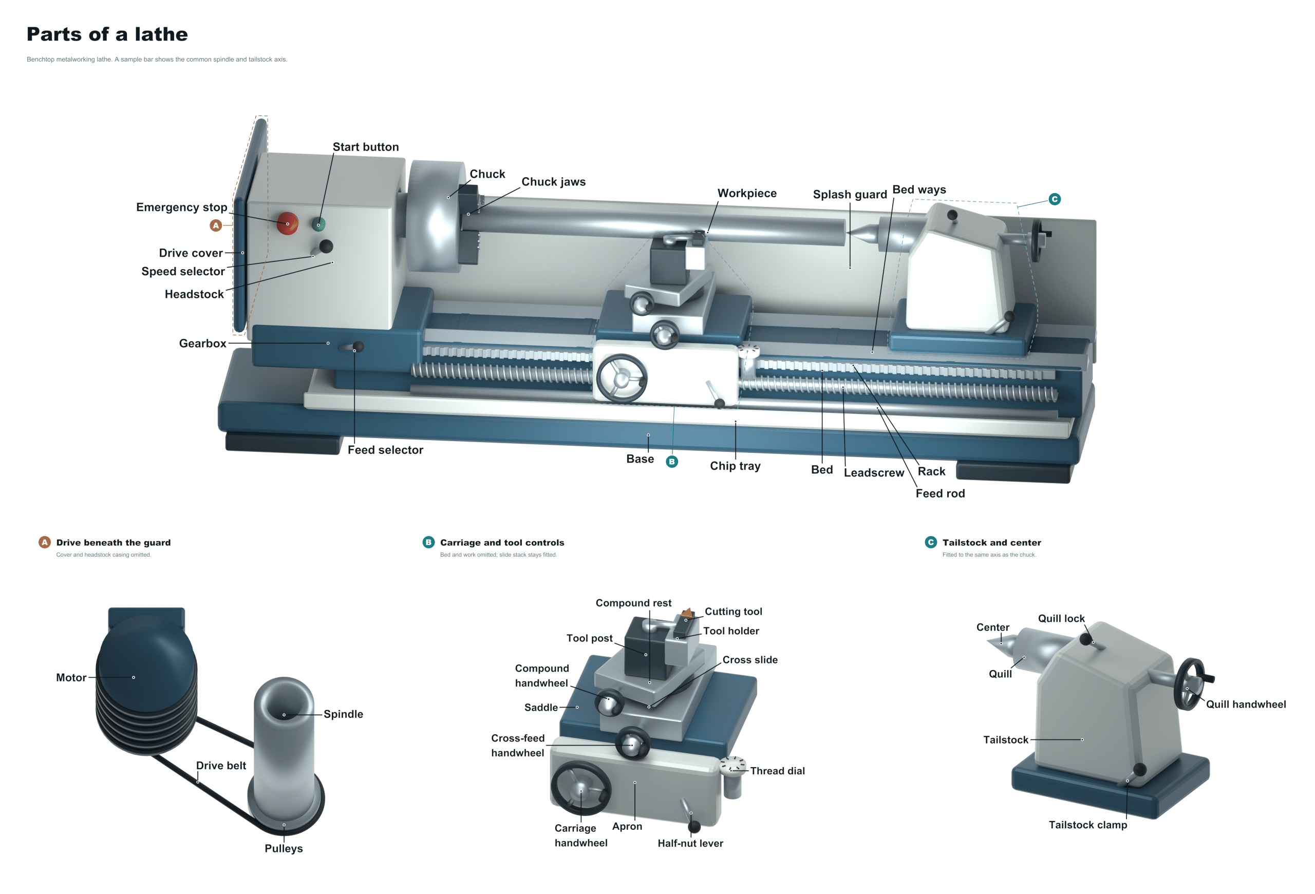
The lathe is an essential machine tool used both in woodwork and metalworking. In these processes, the lathe shapes the workpiece by turning it around an axis. As a cutting tool removes material, it create a precisely shaped part, threading, or even a smooth surface. Once you know how the lathe works, where the components are, and what they do, you will be able to operate one efficienty and safely. Using the labelled diagram above, we’ll identify the parts and explain their purpose in relation to the machining process. I’ve arranged the layout so that it traces the route of operations from the source of power to the support structures.
Without a reliable motor, the lathe cannot maintain the steady speed required for precision work. A good motor not only supplies the rotational force that powers the whole machine but also consistently applies torque to cut materials. The torque may be transferred either directly by coupling or via belts into the inner workings of the lathe.
Parts of the Lathe
Gearbox
From the motor, the torque and rotational speed are sent to the gearbox. This gearbox house a series of gears which can be selected to provide different speeds depending on diameter and material types. For example you could have one configuration for heavy removal at slow speeds and another for fast finishing cuts.
The operator can control the rate of rotation of the machine either before it starts, or whilst it is running. These is called the Speed Controls, which are usually mechanical levers or variable frequency drives that link into the gearbox. Choosing the correct speed for your machining operation will give you a smooth surface finish on the workpiece and stop any tool chatter.
Headstock
On the left is the Headstock. This is where the drive mechanism and spindle is located. The headstock is rigidly mounted to the machine and also supports the rotational forces applied by the cutter as it cuts. The weight of the headstock will dampen any vibration. This damping is key to accurate cuts.
Spindle
Within the headstock, the Spindle is the main rotating piece which holds the chuck that grips your workpiece for spinning. It’s connected directly to the drive system and spins extremely accurately. The condition of the spindle bearings will determine the part’s accuracy and how much runout there is.
Chuck
Mounted on the spindle, there’s also a clamping device called the Chuck which holds the workpiece. For round stock you’d have a three-jaw self-centering chuck; for irregular shapes, you’d use an independent-type four-jaw chuck. Before any cutting takes place, securely fasten your material in the chuck.
This is the long, rigid part of the lathe that carries everything else, such as the headstock and tailstock. This keeps them in perfect alignment with one another and gives a solid foundation upon which the whole machine can be placed. Cast iron is a common material used to make the bed as this helps dissipate vibration and stop the bed from deforming over time.
Bed
A bed has a set of precision-ground surfaces running its length called The Ways. These guides run the carriage back and forth on the table with very little friction. Keeping the surface clean and using proper lubrication is critical to a smooth-running and accurate machine over time.
Lead Screw
A lead screw is a threaded shaft that runs parallel to the bed and engages the carriage to cut threads. The lead screw will rotate at a specific ratio to the spindle which enables the tool to follow along as the work piece turns. This process allows for an accurate screw thread to be cut into the material.
Feed Rod
Cross-feed It is a longitudinal-feed rod. This is a feed rod. This smooth shaft moves the carriage automatically via the feed mechanism. It’s what causes the tool to creep forward evenly under its own power. No more human involvement required! That makes for consistent cuts while also saving your arms from burning out after extended use.
Carriage
This is known as the Carriage, which is the complicated part that rides on the bed ways and supports the cutting tool. The carriage not only supports the weight of the tool post but can also be moved manually or by power. Rigidity here is a must to avoid any bending in harder cutting materials.
Saddle
The saddle is the lower section of the carriage that rides directly on the bed ways. This move along the length of the machine as a result of its support for the cross slide. A good, maintained saddle will align the tool to the axis of rotation.
Cross Slide
Moving in a direction at a right angle to the spindle axis, the Cross Slide is located above the saddle and permits the tool to move toward (or away) from the work piece as required. For example, when doing facing operations, or when turning a diameter, precise cross slide control is essential for adjusting depth-of-cut.
Compound Rest
Mounted on the cross slide, the Compound Rest can be swiveled to various angles. This gives you the ability to make very precise adjustments by hand while cutting threads or tapering. This piece gives you fine control during detailed work.
Tool Post
Compound Rest: is a smaller slide that the tool post sits on to allow for fine manual adjustments. When tightening down a tool, it needs to be done well so the cutting tool does not move while being subjected to cutting forces. Tool Post can be positioned (and adjusted) so that the cutting edge lines up with the spindle’s center line. To do this you would of use the Compound Rest to set the position.
Handwheel
A handwheel rotates by hand to move the cross slide, carriage, or compound rest. Rotating the wheel causes gears to convert rotation into linear motion. This enables fast positioning and makes fine adjustments possible when setting up or turning by hand.
Apron
The Apron is the front panel of the carriage that contains the gears and levers for feed and threading operations. The mechanism that engages the feed rod (or lead screw) is in the apron. The levers on the apron are used by the operator to toggle between automatic and manual mode.
Tailstock
On the far side of the bed from the headstock is the moveable part called the Tailstock. The tailstock holds drill bits, reamers, etc., or it holds the remaining portion of a long piece being worked on. If the tailstock isn’t in alignment with the center of the spindle, your pieces will not be centered and you run the risk of breaking them.
Quill
Within the tailstock, the piece of tubing known as the Quill contains the center or tool and slides in and out on a lever or hand wheel. By moving this forward or backward against the turning workpiece you can grip live centers, or drive your drill bit through. The Quill itself is a hollow, telescoping tube.
Chip Pan
The chip pan catches all the coolant and shavings that drop down from where you are machining. It keeps your floor clean, and when you finish a job it can be emptied out for easy cleanup. Don’t let chips get in the way of moving your tailstock and carriage; empty this regularly.
Leg / Stand
It is a lathe. The leg or stand supports the lathe, raising it to the ideal working height while bearing all its weight. Stability under load is improved, as is vibration reduction, with a solid stand. It’s crucial that the stand be properly leveled so that the geometry of the machine stays accurate.
The lathe is a system of interconnecting parts that all function together to turn raw material into exacting parts. Tool sharpness, way lubrication, and chuck alignment are the first places to look if your lathe is vibrating or exhibiting poor surface finish. Maintaining each of those parts will result in reliable operation of the lathe for years to come.